draw line by bearing and distance civil 3d
You tin use the Line Past Direction and Distance command to draw AutoCAD LINE segments with precision, by referencing bearings and distances, locations selected in the drawing, or COGO points.
To use the Bearings option to define direction
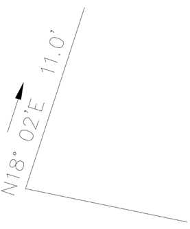
The following example shows how y'all can employ the Line By Management and Distance control to draw a line from the endpoint of a previously fatigued line, at a bearing of Northward 18° 02' E, at a distance of 11.0 feet.
- In the Toolspace, on the Toolbox tab, expand Miscellaneous Utilities
 Coordinate Geometry. Double-click Line by Direction and Distance.
 - Select the finish of a line from which the segment volition be drawn.
- At the control line, enter the quadrant number (i=North East, ii=South East, three=Southward Due west, 4=N Due west). For this example, enter ane.
- Enter the bearing, the direction of the line segment being drawn, in Decimal DMS format: DD.MMSS. For this instance, enter xviii.02.
- Enter the altitude of the segment being fatigued. For this example, enter xi.
- You tin can draw additional segments from the last endpoint or press Enter to end the command.
To use the Azimuth selection to define direction
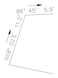
The following instance shows how y'all can use the Line By Direction and Distance command to draw a line from the endpoint of a previously drawn line, at an azimuth of 86° 45', at a distance of five.9 feet.
- In the Toolspace, on the Toolbox tab, expand Miscellaneous Utilities Coordinate Geometry. Double-click Line by Direction and Distance.
- Select the endpoint of a previously drawn line to serve as the get-go point of the new line.
- At the command line, enter A to use the Azimuth way.
- Enter an azimuth, the management of the line segment existence drawn, in Decimal DMS format. For this example, enter 86.45.
- Enter the altitude of the segment being drawn. For this example, enter 5.ix.
- You lot can describe boosted segments from the last endpoint or printing Enter to stop the control.
To select locations on screen to define direction
Y'all can select locations to ascertain the management when using the Line by Management and Distance command. This is useful when you accept previously drawn an entity on the screen, and you lot want to copy its direction for a new line, but start the new line from a different location. Turning on OSNAPs will ensure precise point selections.
- In the Toolspace, on the Toolbox tab, expand Miscellaneous Utilities Coordinate Geometry. Double-click Line past Direction and Distance.
- Select the start point of the segment to be drawn.
- At the control line, enter P to employ the screen point mode.
- Define a direction by selecting a starting location, then select an ending location. Note the two screen selections may be anywhere in the model, and may not necessarily include the starting betoken of the line segment.
- Enter the altitude of the segment being drawn.
The command continues, and boosted segments volition be drawn from the last endpoint.
To specify COGO bespeak locations to ascertain the direction and/or distance
When using the Line By Direction and Distance control, you can enter COGO point locations to ascertain the management, and/or the distance, in conjunction with standard Autodesk Civil 3D transparent commands. This is useful when you want to describe a line using the direction from a pair of points and you want the distance to equal the altitude from a pair of points.
The post-obit example shows how you can use the Line By Direction and Distance command to draw a line from bespeak v, parallel to line 2-3, with a distance equivalent to 2-1, and and then a closing line parallel to ane-ii and endmost on line two-3.

- In the Toolspace, on the Toolbox tab, aggrandize Miscellaneous Utilities Coordinate Geometry. Double-click Line by Direction and Distance.
- At the control line, enter 'PN to use the point number transparent control.
- Enter the point number at the control line prompt. For this example, enter v.
- At the command line, enter P to use the screen option mode.
- The transparent command 'PN is still activated, then you tin enter the point numbers to define the direction. For this instance, enter 2 for the first direction point, and 3 for the second direction point.
- Enter the point numbers to ascertain the distance. For this example, enter 2 for the first altitude signal, and one for the 2nd distance signal to draw the first segment.
- Enter P to re-enter point manner, and then enter the points to define the closure management. For this example, enter 1 and 2.
- Define the length of the closure line. For this example, enter v, and so ii.
- Printing Enter to end the command.
Source: https://knowledge.autodesk.com/support/civil-3d/learn-explore/caas/CloudHelp/cloudhelp/2021/ENU/Civil3D-UserGuide/files/GUID-832B9B5C-1B86-4228-81D0-CA1C58874F64-htm.html#:~:text=To%20use%20the%20Bearings%20option%20to%20define%20direction&text=In%20the%20Toolspace%2C%20on%20the,the%20segment%20will%20be%20drawn.
0 Response to "draw line by bearing and distance civil 3d"
Enviar um comentário